
Higher cut off frequency for line- and frequency filters extends range of WT5000 Precision Power Analyzer
by Andreas Maushammer June 25, 2024Yokogawa’s WT5000 Precision Power Analyzer already offers exceptional features to users, including a high measurement accuracy of ± 0.03 % as well as unrivalled stability, noise immunity and supreme flexibility based on plug-in modules.
The firmware 3.31 or later makes the WT5000 even more useful, with the maximum cut off frequency of the digital line- and frequency filters, rising from 100 kHz to 300 kHz. With the trend towards higher switching frequencies, this allows higher frequency spectra to be measured, while at the same time suppressing interfering frequency components. This new and higher cut off frequency can be used in two different filter modes.
1) The frequency filters, placed parallel to the measurement path
Frequency filters are used to detect the fundamental period in waveforms made up of mixed frequencies. Usually a low-pass filter, adjustable from 100 Hz to 300 kHz is used for this purpose. However, a high pass filter, selectable from 0.1 Hz to 100 kHz, or a combination of both in the form of a band-pass filter, can be set in the WT5000. See figure 1.
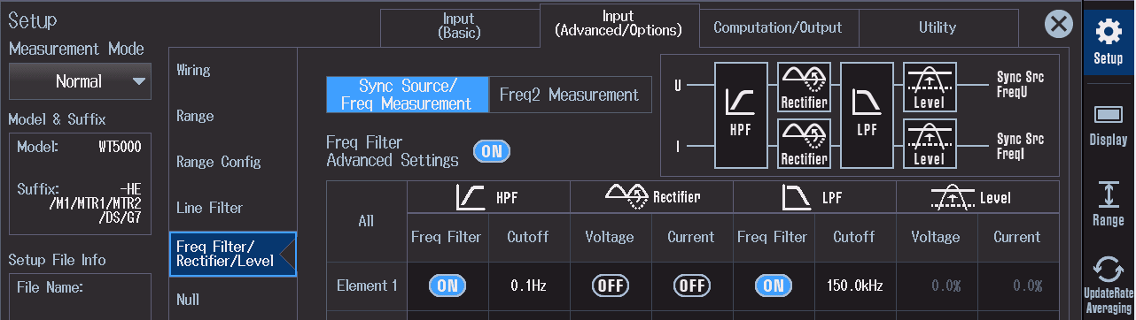
Figure 1: The frequency filters are used to determine the fundamental period from frequency mixtures. Normally a low-pass filter is used for this purpose, but a band-pass filter can also be set.
With the aid of the frequency filter, the WT5000 can clearly detect the zero crossings (edges) of the fundamental oscillation. This makes it possible to measure the fundamental frequency and therefore synchronize the measurement to complete signal periods. The frequency filter is also important for the generation of a stable reference frequency for harmonic analysis in order to ensure leakage error-free measurement values.
In general, the correct synchronization to the fundamental frequency is essential for the accurate determination of interval-related quantities. For example, for power measurement values, as well as RMS values of voltage and current.
Especially noteworthy is the fact that the frequency filter has no influence on the signal amplitude which need to be measured. The filter is placed in a separate path, parallel to the measurement path and is used exclusively to identify the fundamental frequency for synchronization to complete periods.
2) The line filters, located in the measurement path
Line filters can be used to attenuate higher frequency noise and suppress any aliasing by reducing the measurement bandwidth. In the WT5000, this is implemented on the one hand as a digital fourth-order low-pass filter. The user can choose between the Butterworth or Bessel characteristic and cut-off frequencies from 100 Hz to 300 kHz. See figure 2.
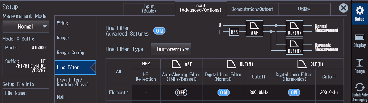
Figure 2: If required, the digital line filter can be switched on to attenuate high-frequency interference components. With the now higher cutoff frequency of up to 300 kHz, a sufficient measurement bandwidth is also provided for applications with higher-frequency spectral components.
On the other hand, an analog 1 MHz line filter with a Bessel characteristic (fifth-order) is also available. When using the line filter, the user should be aware that too low cut-off frequencies can lead to inaccurate or even unusable measurement results. For this reason, all filters at Yokogawa power analyzers are completely switched off by default – because in the end, measurements without filters represent the spectrum (the reality) best.
Excluded from this is the frequency filter, since this filter is placed parallel to the measurement path and therefore has no influence on the signal which need to be measured.
So which cut-off frequencies are recommended for the line filter? This depends on the relevant frequency spectrum to be measured or the specific measurement task. With individually adjustable cutoff frequencies in the range from 100 Hz to 300 kHz and the 1 MHz analog filter, the user has a wide range of options for selecting the best setting for the application.
In applications with frequency converters, the use of the WT5000´s 1 MHz analog filter will be appropriate for most cases to suppress high-frequency interference peaks that are insignificant for the power measurement. In addition, aliasing can be reliably excluded with the 1 MHz line filter, which is very unlikely anyway due to the high sampling frequency of the A/D converter (10 MS/s).
With the digital line filters up to 300 kHz, the user benefits at measurements in environments with particularly high EMC, since high-frequency interference components are now further attenuated, while at the same time, a sufficient measurement bandwidth is ensured. The WT5000 is therefore more capable than ever and gives users more options to develop successful new products and solutions.
For more information on the WT5000, make sure you visit our website or reach out to us by clicking here.

No Comments so far
Jump into a conversationNo Comments Yet!
You can be the one to start a conversation.